CNC Lathe Tool Setting Method
CNC Lathe Tool Setting Method
- Dec 08, 2024
What Is "Tool Setting" in CNC Machines?
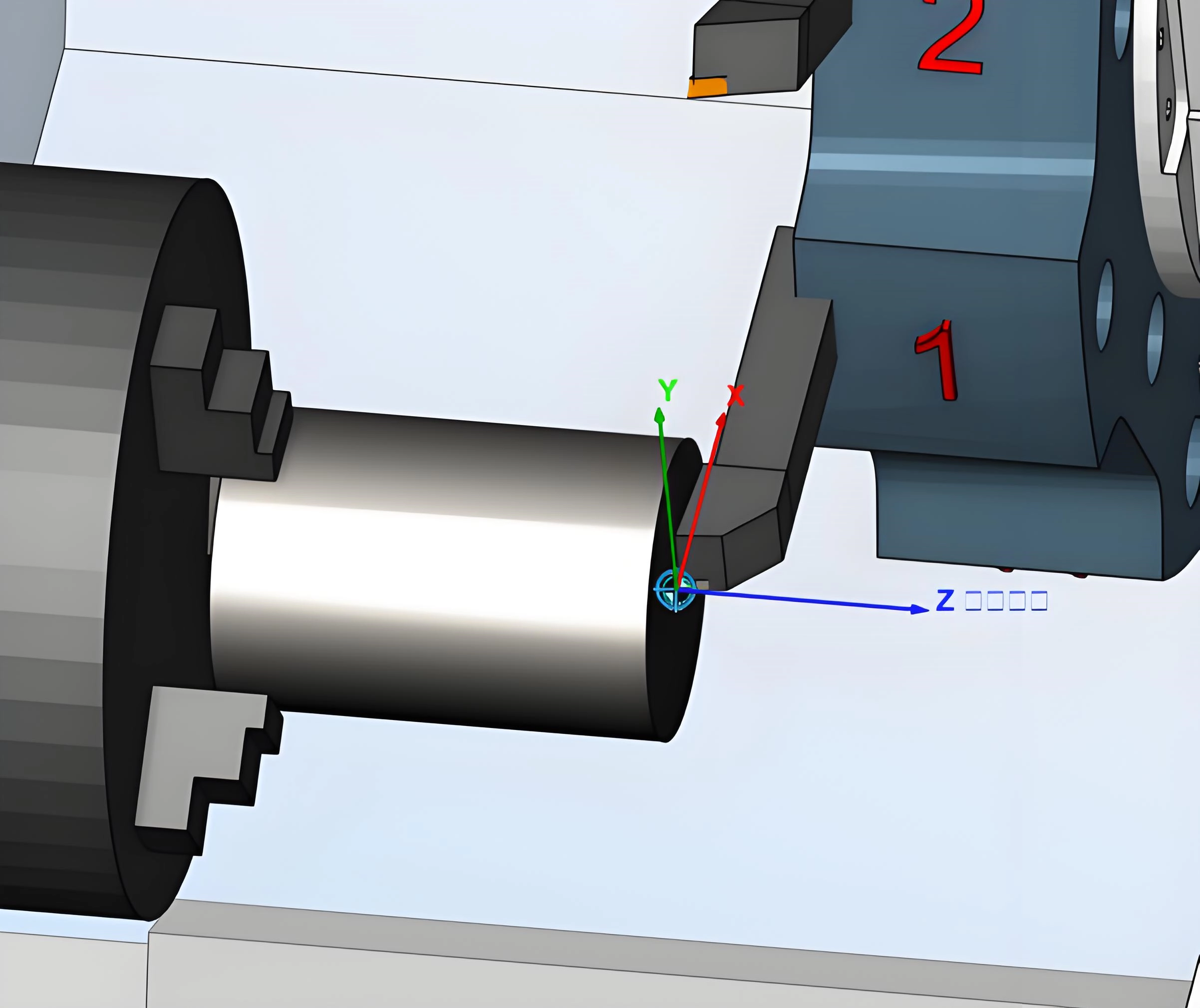
In CNC machining operations, the tool setting refers to a series of operations performed to determine the relative positional relationship between the tool and the workpiece or machine reference point, and then input this data into the CNC system to ensure the machine can accurately complete the machining process according to the program. Simply put, it is about telling the machine "where the tool is currently located," thereby enabling the system to calculate the tool's movement trajectory.
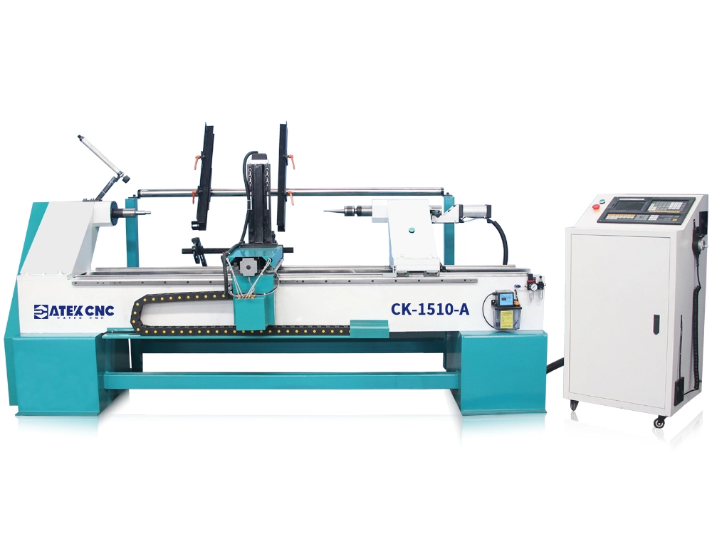
Tool setting operations are closely related to workpiece dimensions and the tool itself: the former corresponds to the establishment of the coordinate system zero point during machining; the latter requires special attention in ATC CNC lathes—since different tools vary in length, diameter, tool tip angle, and position, each tool must undergo individual tool setting.
How to Perform Tool Setting on a CNC Wood Lathe?
Manual tool setting
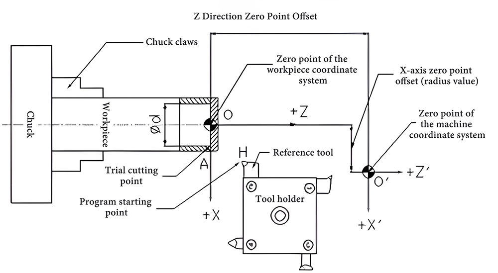
First, the zero point must be established. Typically, the reference point of the lathe (such as the spindle chuck or the tip) is selected as the zero point. Auxiliary positioning is then performed based on the chosen reference point. Using the handwheel, the tool tip is slowly moved to the selected position, and the XYZ coordinates are reset to zero.
Once the zero point is set, the coordinate difference between the tool tip and the workpiece position must be corrected. The trial cutting method is widely used for tool setting on CNC lathes. This method utilizes test cuts to measure and calculate the current zero point position deviation, thereby assisting in establishing the workpiece coordinate system. The specific steps are as follows:
- Install the tool securely and fix the workpiece firmly.
- Move the tool near the workpiece using the handwheel or manual mode, then lightly touch the wood surface.
- Make a light cut along the X-axis (maintaining the X-coordinate, then retract along the Z-axis after cutting). After cutting, measure the diameter of the machined surface and calculate the compensation value (some control systems, especially those on metal lathes, support automatic compensation—simply input the measured value).
- Repeat the process for facing (cutting along the Z-axis while keeping the coordinate constant, then retracting along the X-axis). Calculate the Z-axis compensation value.
- Recalibrate the zero point based on the compensation values.
Automatic tool setting
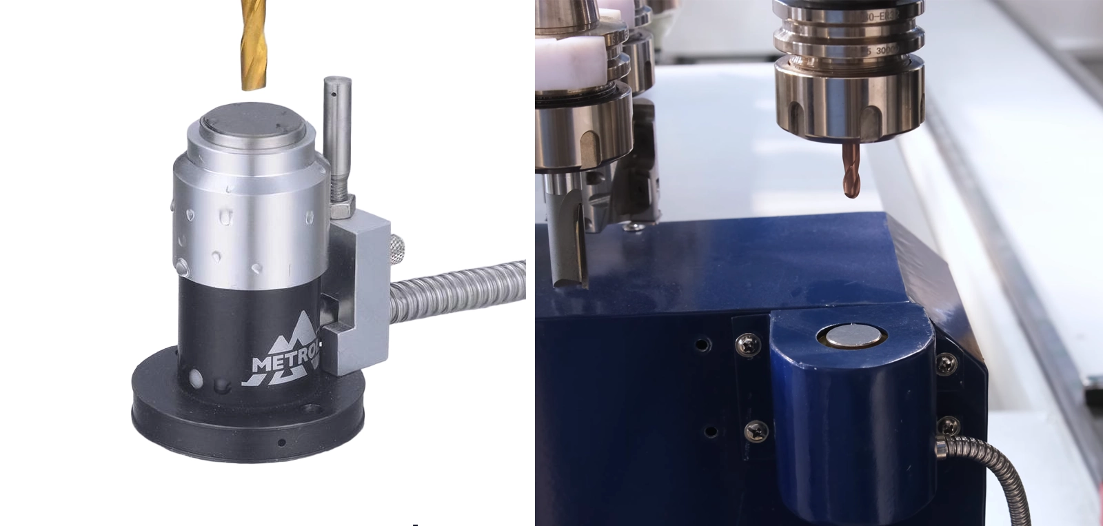
If multiple tools are required during the machining process and tool setting operations must be performed after each tool change, the entire machining process would become nearly unfeasible if manual tool setting were adopted.
The automatic tool setter simplifies the measurement and calculation of tool tip position compensation after automatic tool changes, enabling continuous automated machining on ATC CNC wood lathes. However, this device still cannot completely replace manual tool setting (it provides no assistance in establishing the zero point or workpiece coordinate system). For metal milling machines or metal lathes, the establishment of the workpiece coordinate system is typically facilitated by a probe, which will not be elaborated upon here.
RELATED MODELS
We recommend some related models for you...
