What Is a Servo Motor?
What Is a Servo Motor?
- Aug 28, 2025
To understand what a servo motor is, you first need to know several relevant professional terms.
Open-Loop Control
A control system in which the output quantity has no impact on the system's control is called an "open-loop control system".
Open-loop control is a control method that acts on the controlled object unidirectionally only through preset instructions. Its core feature is the absence of a feedback loop in the system structure. After the controller generates an operation instruction based on the initial setting, it acts directly on the actuator; the actual state of the controlled quantity cannot be returned to the input end through a measuring element for deviation correction.
Closed-Loop Control
In a control system, if the controlled quantity of the system is fed back and the output can be corrected based on the output feedback of the controlled object, this type of control system is called a "closed-loop control system".
From the perspective of signal flow in the system, the output signal of the system returns to the input end of the system along the feedback channel, forming a closed channel—hence the name "closed-loop" control system. This system is also known as a "feedback control system".
Stepper Motor
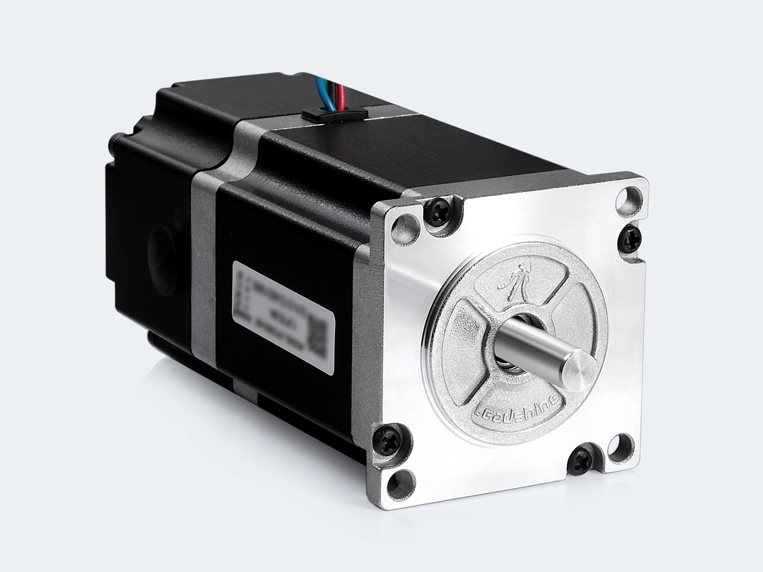
A stepper motor is an electric motor that converts electrical pulse signals into corresponding angular displacement or linear displacement. For each input pulse signal, the rotor rotates by an angle or moves one step forward. The output angular displacement or linear displacement is proportional to the number of input pulses, and the rotational speed is proportional to the pulse frequency. Therefore, a stepper motor is also called a "pulse motor". In a broad sense, a stepper motor is a brushless DC motor controlled by pulse signals, and can also be regarded as a synchronous motor whose speed is synchronized with the control pulse frequency within a certain frequency range.
The stepper motor was invented relatively early and has a long application history. Its initial model can be traced back roughly to the period between 1830 and 1860. Around 1870, attempts began to use it for control purposes, specifically in the electrode delivery mechanism of argon arc lamps. During World War II, stepper motors were widely used, mainly in military equipment such as artillery control systems and the drive systems for control surfaces (rudder surfaces) of ships and aircraft. The period from 1960 to 1970 was the golden age of stepper motor development; during this time, in addition to the military field, stepper motors were also widely used in industrial automation.
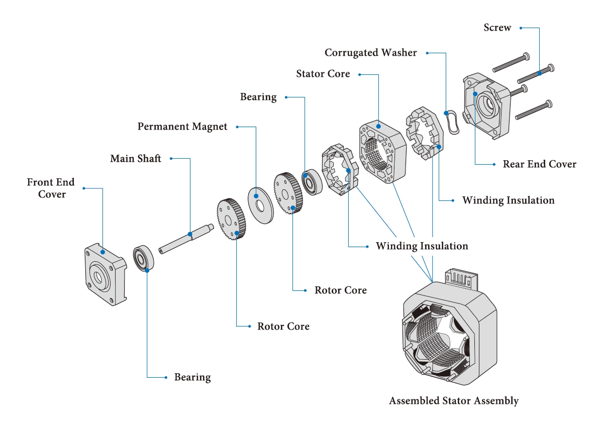
Structure of stepper motor
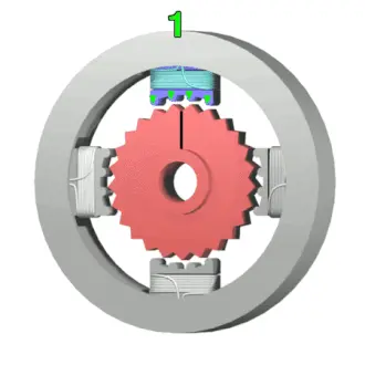
Operation animation of stepper motor
Frame 1: The electromagnet (1) is energized, attracting the nearest teeth of the gear-shaped iron rotor. With the teeth aligned to electromagnet (1), they will be slightly offset from right electromagnet (2).
Frame 2: The top electromagnet (1) is turned off, and the right electromagnet (2) is energized, pulling the teeth into alignment with it. This results in a rotation of 3.6° in this example.
Frame 3: The bottom electromagnet (3) is energized; another 3.6° rotation occurs.
Frame 4: The left electromagnet (4) is energized, rotating again by 3.6°. When the top electromagnet (1) is again enabled, the rotor will have rotated by one tooth position; since there are 25 teeth, it will take 100 steps to make a full rotation in this example.
Servo System
"Servo" is an abbreviation of the term "Servo Mechanism", which originates from Greek and means "slave". As the name implies, it refers to a system that follows external instructions to perform the desired motion, where the motion elements include physical quantities such as position, speed, and torque.
A servo system is an implementation and typical application of a closed-loop control system. Looking back at the development history of servo systems—from the earliest hydraulic and pneumatic systems to today's electrified systems—the servo system, composed of a servo motor, a feedback device, and a controller, has been in existence for nearly 50 years.
Servo Motor
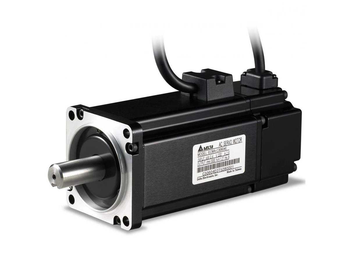
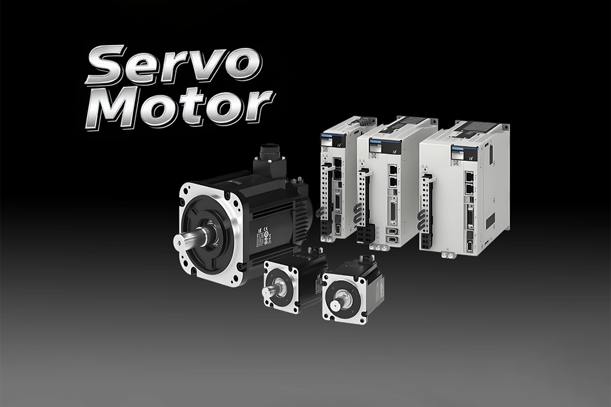
The servo motor is an electric motor that controls the operation of mechanical components in a servo system. It is an auxiliary motor indirect speed change device and is one of the three core components in a servo system.
The "servo motor" we usually refer to actually generally means the entire servo system that includes the motor, feedback device, and controller.
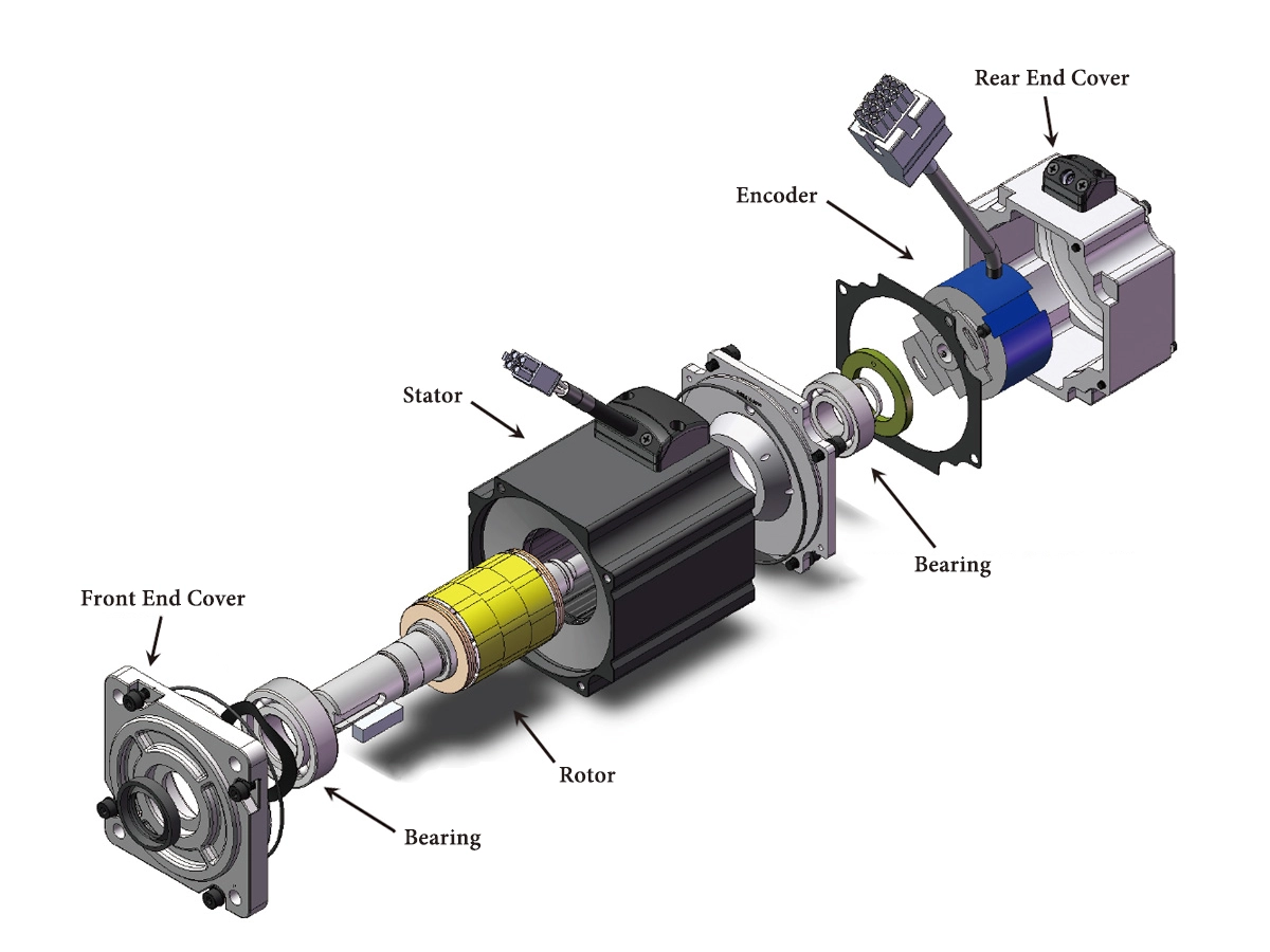
Structure of servo motor
Types of Servo Motors
Classification by Motor Structure
Servo motors can be divided into multiple types according to different classification criteria.
- AC servo motor
This is definitely the mainstream and first choice in current industrial automation, occupying most of the market share.
It is based on frequency conversion and vector control technologies, and controls the motor's speed and torque by changing the output frequency, voltage, and phase of the driver.
It can be divided into permanent magnet synchronous motors and asynchronous servo motors
- DC servo motor
This is the most mature servo motor with the longest history. However, with the maturity of AC servo technology, its application has gradually decreased.
It changes the motor's speed and torque by controlling the armature voltage or excitation current.
It can be divided into brushed DC servo motors and brushless DC servo motors.
Classification by Feedback Device Type
- Photoelectric encoder type
The most commonly used type. It is divided into incremental encoders (low cost, requiring zero return) and absolute encoders (capable of directly obtaining absolute position without zero return, more high-end).
- Resolver type
Extremely robust and durable, resistant to shock, oil pollution, and high temperatures. It is often used in extreme environments (such as military industry, aerospace).
- Hall sensor type
Usually used for simple commutation of brushless DC motors, with low precision.
Servo Motor vs Stepper Motor
| Servo Motor | Stepper Motor | |
|---|---|---|
| Control Method | Closed-loop control | Open-loop control |
| Working Principle | Relies on encoder feedback for real-time error correction to ensure reaching the target. | Rotates by a fixed angle (step angle) each time a pulse signal is received. |
| Precision | Very high. Precision depends on the resolution of the encoder, which is usually much higher than that of stepper motors. | High. Precision is determined by the step angle, but without feedback, there is no way to know if step loss occurs. |
| Torque Characteristic | Provides constant rated torque within the rated speed range, with strong overload capacity (usually 3 times overload for a short time). | High torque at low speeds, but torque decreases sharply as speed increases (there is a torque decay issue). |
| Performance | High performance. High speed (can reach several thousand or even tens of thousands of revolutions per minute), takes only a few milliseconds to accelerate from a standstill to its rated speed, with fast response, suitable for dynamic loads and high-speed applications. | Moderate performance. Maximum speed is usually within 1000 RPM, takes 200-400 milliseconds to accelerate from a standstill to the operating speed (generally several hundred revolutions per minute), poor high-speed performance, and prone to vibration and heat generation. |
| Complexity / Cost | Complex and expensive. Requires a driver and an encoder, and debugging is more complex. | Simple and low-cost. The driver is simple, and it is easy to install and use. |
| Reliability | High, but the system is more complex with slightly more potential failure points (e.g., encoder). | Very high. Simple and robust structure, and brushless motors have a longer service life. |
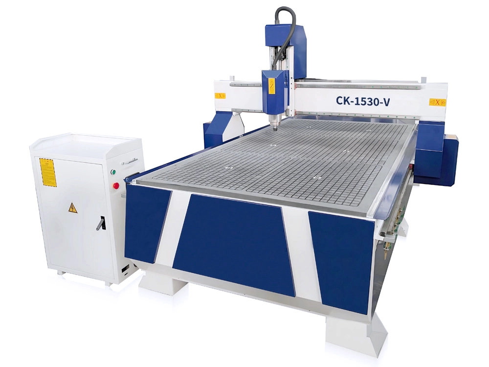
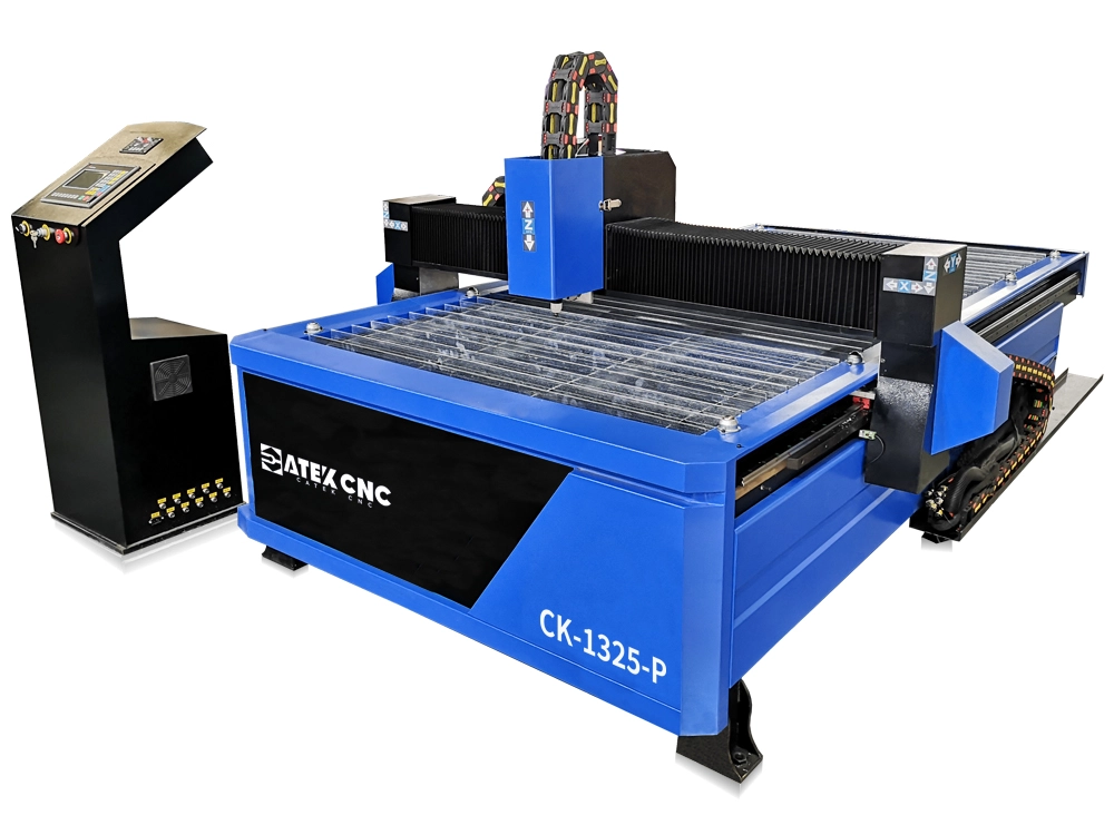
| Application Scenarios | CNC machine tools, industrial robots, semiconductor equipment, high-precision automation equipment, and occasions requiring high speed and high response. | Low-cost positioning occasions such as 3D printers, desktop CNC machines, scanners, and fax machines. |
| Step Loss Issue | No step loss, as feedback is available for continuous correction. | Step loss may occur. If the load torque exceeds the motor torque, the motor will lose steps or overshoot, and the system cannot detect this. |
| Vibration & Noise | Runs smoothly and quietly, especially at low speeds. | May have vibration and noise at low speeds (but can be improved with a micro-stepping driver). |
Note: The compared objects herein are the servo motor (encoder-type AC permanent magnet synchronous servo motor) and open-loop stepper motor commonly used in CNC machine tools.
In fact, there is another type of motor available on the market, known as the closed-loop stepper motor.
A closed-loop stepper motor is essentially a combination of a traditional stepper motor, an encoder, and a control algorithm. By adding a real-time position feedback (encoder) to the traditional open-loop stepper system, it solves the latter’s biggest pain point — step loss or overshoot.
Since the closed-loop stepper motor addresses the step loss issue, it can achieve relatively high rotational speeds. Additionally, it is usually more cost-effective than a servo motor system with equivalent torque.
RELATED MODELS
We recommend some related models for you...
